Das PRAKLA-SEISMOS Vibrator-System VVCA
Teil 1
Zu Beginn der 60er Jahre wurden für die Reflexionsseismik mehrere Verfahren entwiclcelt, deren Ziel es war, vom 5prengstoff loszukommen und als Energiequelle mechanisch erzeugte Impulse zu verwenden.
Auch für die PRAKLA stellte sich zu dieser Zeit die Frage, welche der angebotenen sprengstofflosen Methoden die meiste Aussicht auf Erfolg haben würde. Dr. H. W. Maaß, der damalige Leiter unserer Technischen Abteilung, fällte die richtige Entscheidung, als er sich für die Einführung des VIBR0SEIS-Verfahrens entschloß, denn die anderen sprengstofflosen Methoden spielen bekanntlich heutzutage in der Reflexionsseismik eine ziemlich untergeordnete Rolle.
Der Vibrator ist ein wesentlicher Teil im VIBR0SElS-Verfahren. Unsere Gesellschaft entwickelt und baut Vibratoren seit vielen Jahren für die eigenen Trupps und bietet sie seit einiger Zeit mit gutem Erfolg auch zum Verkauf an.
Über das eigentliche VIBR0SEIS-Verfahren und die Arbeit unserer VIBR0SEIS-Trupps in aller Welt ist in unserer Zeitschrift schon öfters berichtet worden, wobei die Vibratoren nur am Rande erwähnt wurden. Es schien uns nun an der Zeit, auch die Funktion und die "Arbeit" der Vibratoren etwas ausführlicher zu beschreiben und damit die Serie der bisher erschienenen Artikel zu ergänzen und abzurunden.
Aus technischen Gründen mußte der folgende Artikel in zwei Teile gegliedert werden. Der zweite Teil wird in der Folge 3/75 unseres Report erscheinen. Da er aber in der Druckerei bereits vollständig gesetzt wurde, kann er von Interessenten schon jetzt als Sonderdruclc ungeteilt angefordert werden.
Die Redaktion* Trademark of Continental Oil Comp.
Von allen seismischen Oberflächenverfahren, bei denen die seismische Energie ohne Verwendung von Sprengstoff erzeugt wird, hat das VIBROSEIS*)-Verfahren die mit Abstand größte Verbreitung gefunden. Die Technologie des Verfahrens beinhaltet eine Fülle von Anwendungsmöglichkeiten für die Seismik. Die Ausnutzung dieser Möglichkeiten für die Suche nach neuen Kohlenwasserstofflagerstätten stellen Techniker und Wissenschaftler immer wieder vor neue Entwicklungsaufgaben.
At the beginning of the '60s, several methods for reflection seismics were developed, with the aim of getting away from explosives and using mechanically generated impulses.
At that time, also for PRAKLA the question arose, which one of the non-explosive methods offered would be the most successful. Dr. H. W. Maaß, at that time head of the Technical Department, made the right decision 'when he decided to introduce the VIBROSEIS-method -as nowadays all the other non-explosive methods playarather minor part in reflection seismics.
The vibrator is an essential part of the VIBROSEIS-system. For many years our company has developed and built vibrators for our own crews and has also sold them succussfully for some time.
In our PRAKLA-SEISMOS Report we have repeatedly reported upon the actual VIBROSEIS-method and the work of our VIBROSEIS crews all over the world, whereby the vibrators were mentioned only in passing. Perhaps we should now describe the function and the "work" of the vibrators in more detail and therewith complete and round off the series of articles published so far.
For technical reasons, the following article had to be written in two parts. The second part will be published in No. 3/75 of our PRAKLA-SEISMOS Report. But as it has already been printed, it can be ordered now by those interested as a "special print" in one part.
The editorPRAKLA-SEISMOS vibrator system VVCA
First Part Of all seismic surface methods where seismic energy is generated without the use of explosives, the VIBROSEIS*) method is the most popular. The technology of this method comprises many modes of application for seismics. The exploitation of these possibilities in the search for new hydrocarbon deposits brings, repeatedly, new development problems for technicians and scientists.
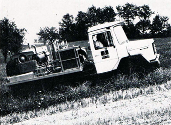
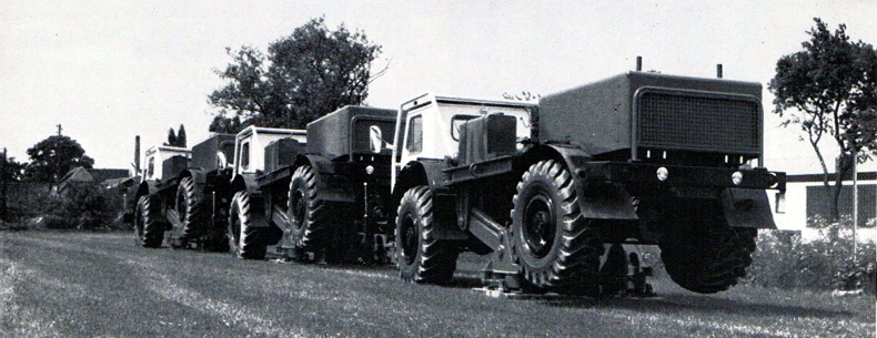
Fig. 1 VVB Vibrator-Anlage
Ein neuer Beitrag von PRAKLA-SEISMOS zur Erfüllung dieser Aufgaben ist das in Eigenkonstruktion entwickelte " Integrierte Vibrator-System VVCA". Es befindet sich seit Juni 1975 im routinemäßigen Einsatz.
PRAKLA-SEISMOS verfügt auf dem Gebiet des Vibratorbaus über eine etwa 10jährige Erfahrung, die sich, gestützt auf den langjährigen Einsatz unserer VIBROSEIS Meßtrupps in vielen Ländern Europas, des Nahen Ostens und Afrikas, durch besondere Praxisnähe auszeichnet.
Mit der Zunahme unserer VIBROSEIS-Trupps entstand der Wunsch nach einem besonders geländegängigen Vibrator System, das unser bisheriges Bauprogramm ergänzt und erweitert. Die Entwicklung führte zur Konstruktion des Vibrator-Systems (VVCA), das sich von dem einer herkömmlichen Vibrator-Anlage zum Teil wesentlich unterscheidet.
Bevor wir uns mit einigen technischen Details näher befassen, sollen noch ein paar allgemeine Bemerkungen über die Funktion und Arbeitsweise eines Vibrators vorausgeschickt werden.
Das Vibrator-System VVCA ist ein Spezial-Gerät, das, ebenso wie sein "Verwandter", die Vibrator-Anlage VVB, zur Erzeugung von Schallwellen in der Seismik dient.
Die eigentliche Vibrator-Einheit, mit der die Schallwellen erzeugt werden, und ihre Energieversorgungsanlage sind auf dem Fahrgestell des Fahrzeuges aufgebaut, das die Aufgabe hat, den Vibrator auf Arbeitsposition zu bringen.
Mit Hilfe eines Spezialliftsystems wird der Vibrator in Arbeitsstellung gebracht, d. h. auf den Boden abgesetzt. Damit die Vibratorbodenplatte während des Vibrierens nicht vom Boden abhebt, muß sie mit einer Kraft angepreßt werden, die größer ist als die Kraftamplitude des Vibrators. Das Liftsystem wird daher soweit ausgefahren, bis das Fahrzeugheck vom Boden abhebt. Der Vibrator ist zwischen der Hinterachse und dem Fahrzeugschwerpunkt angebracht, so daß bei Arbeitsstellung nahezu das gesamte Fahrzeuggewicht auf der Vibratorbodenplatte lastet und somit ein Maximum an Anpressung erreicht wird. Luftfederelemente, die zwischen Vibrator und Liftsystem eingebaut sind, verhindern, daß die Schwingungen des Vibrators auf das Fahrzeug übertragen werden.
The integrated vibrator system VVCA, developed by PRAKLA-SEISMOS, is a new contribution to the realization of these tasks. The system has been in routine application since June 1975.
PRAKLA-SEISMOS can look back on 10-years experience in the field of vibrator construction based on the experience of our VIBROSEIS survey crews in many European countries, in the Near East and in Africa.
With the extension of our work in the field, the need for a special cross-country vibrator system arose, which extends and completes our construction program, so far. This led to the construction of a vibrator system which is, in part, essentially different from the traditional vibrator system.
Before describing in detail some technical aspects of the vibrator system, some general remarks on its function and application will be made.
The vibrator system VVCA is a special unit, which, like its "relative" the vibrator system VVB, is used for generating sound waves in seismics. The vibrator itself, generating the sound waves, and its supply unit, are mounted on a special chassis.
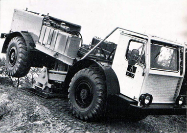
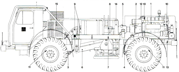
Fig. 2 VVCA Vibrator system
By means of a special lift system the vibrator is brought into working position, i. e. set down on the ground. As the vibrator base-plate should not rise off the ground while vibrating, it has to be pressed down by a force greater than the force amplitude of the vibrator. For this purpose the lift system is let down until the rear of the vehicle leaves the ground. The vibrator is installed between the rear axle and the centre of gravity of the vehicle, so that, in the working position, almost the total weight of the vehicle rests upon the vibrator base-plate and thus a maximum pressure is guaranteed. Air bags, which are installed between the vibrator and the lift system, prevent the oscillations of the vibrator from being transmitted to the vehicle.
The electro-hydraulic vibrator transmits a sinusoidal signal into the subsurface, also called pilot signal or sweep, with a continuously changing sequence of frequency in the range of 5 to 120 Hz as up-sweep (increasing frequencies) or down-sweep (decreasing frequencies). In general, the duration of the signal is between 7 and 16 s.
Der elektrohydraulische Vibrator überträgt ein sinusförmiges Signal, auch Steuersignal oder Sweep genannt, mit stetig steigender (up-sweep) oder fallender (down-sweep) Frequenzfolge im Bereich zwischen 5 und 120 Hz in den Untergrund. Die Zeitdauer des Signals liegt in der Regel zwischen 7 und 16 s. Der Vibrator wird von der Vibratorelektronik gesteuert, die sich im Fahrerhaus befindet. Das Steuersignal wird von einem elektronischen Generator erzeugt, der sich entweder im Meßwagen befindet oder in die Vibratorelektronik eingebaut ist. Im ersten Fall muß das ganze Steuersignal über Funk zur Vibratorelektronik übertragen werden. Im zweiten Fall sendet der Meßwagen nur ein kurzes Code-Signal (Startsignal) aus, das den Steuersignalgenerator in der Vibratorelektronik auslöst.
Ein VIBROSEIS-Meßtrupp verfügt in der Regel über vier Vibrator-Systeme, von denen drei im Einsatz sind. Das vierte System dient als Reserve. Die drei im Einsatz befindlichen Vibrator-Systeme arbeiten nach einem bestimmten Schema, das vorher vom Truppleiter festgelegt worden ist, auf der "Vibrationsstrecke". Sie sind synchronisiert, d. h. das Signal wird von allen Vibratoren gleichzeitig in den Untergrund übertragen. Die Synchronisation muß sehr präzise sein, um den Erfolg der Messungen zu gewährleisten.
Zum besseren Verständnis der folgenden Ausführungen wollen wir den Begriff "Vibrator" an dieser Stelle genauer definieren. Im täglichen, allgemeinen Sprachgebrauch verstehen wir unter einem Vibrator die gesamte Anlage : Fahrzeug, Liftsystem und den Vibrator selbst. Hierfür wollen wir jedoch im folgenden die Bezeichnung Vibrator-System verwenden. Der eigentliche Vibrator, wesentlicher Bestandteil des Vibrator-Systems, setzt sich aus den Baugruppen Steuerteil und Reaktionsteil zusammen.
Wie sehr sich eine Vibrator-Anlage und ein Vibrator-System durch ihre verschiedene Grundkonzeption schon äußerlich voneinander unterscheiden, zeigen die Aufnahmen einer konventionellen Vibrator-Anlage vom Typ PRAKLA-SEISMOS VVB und eines integrierten VibratorSystems vom Typ PRAKLA-SEISMOS VVCA in den Figuren 1 und 2.
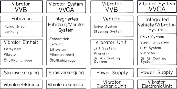
Aus dem Vergleich der Blockdiagramme auf Seite 5 geht hervor, daß das Vibrator-System VVCA ein echtes "System" ist, bei dem Fahrzeug und Vibrator-Einheit voll integriert sind. Bei der Vibrator-Anlage VVB handelt es sich dagegen um einen Lastkraftwagen, auf dem die Vibrator-Einheit montiert ist.
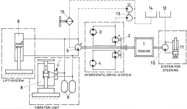
Die unterschiedliche Konzeption der Vibrator-Anlage VVB und des Vibrator-Systems VVCA wird besonders deutlich, wenn man ihre Hydraulik-Schaltschemata miteinander vergleicht, die in stark vereinfachter Form in den Figuren 3 und 4 wiedergegeben sind.
Ein wesentliches Merkmal der Vibrator-Anlage VVB ist das Vorhandensein von zwei Verbrennungsmotoren, von denen einer über Kardanwellen das Fahrzeug antreibt. Ein zweiter Motor, der auf dem Heck des Fahrzeugs montiert ist, liefert die Energie für die Vibrator-Einheit, die sich aus dem Liftsystem, dem eigentlichen Vibrator und der Olluftkühlanlage zusammensetzt.
Aus dem Hydraulik-Schaltschema des Vibrator-Systems VVCA geht hervor, daß nur ein Verbrennungsmotor sowohl für den Fahrantrieb und die Lenkung als auch für den Betrieb des Liftsystems, der Vibratoreinheit und der Olluftkühlanlage vorhanden ist. Die Energieübertragung ist voll hydraulisch.
Block diagram of the vibrator systems VVB and VVCA
The vibrator is controlled by the vibrator electronic unit, which is installed in the driver's cabin. The pilot signal is produced by an electronic generator, which is either in the recording truck or installed in the vibrator electronic unit. In the first case, the entire pilot signal has to be transmitted to the vibrator electronic unit by radio. In the second case, the recording truck transmits only a short code-signa,l (starting signal) which triggers the sweep generator in the vibrator electronic unit.
In general, a VIBROSEIS crew has four vibrator systems at its disposal, of which three are in action. The fourth system is a stand-by unit. The three performing vibrator systems work according to a certain scheme on a vibrator pattern, which has been predetermined by the party chief; the systems are synchronized, i. e. the signal is transmitted into the subsurface simultaneously by all vibrators. The synchronization has to be very precise to guarantee the success of the survey.
For a better understanding of the following details we now define the term "vibrator" . In general use we mean by "vibrator" the whole system: vehicle, lift system and the vibrator itself. For all this, however, we will use in the following description the designation vibrator system. The vibrator itself, essential part of the vibrator system, consists of the structural components control unit and reaction unit.
The photographs in figures 1 and 2 of a conventional vibrator truck, PRAKLA-SEISMOS-type VVB, and of an integrated vibrator system, PRAKLA-SEISMOS-type VVCA, show, how much a conventional vibrator truck and a vibrator system differ outwardly from each other by their fundamental conception.
The comparison of the tables on page 5 shows, that the vibrator system VVCA is a real " system" in which the vehicle and the vibrator unit are fully integrated. On the other hand, the vibrator truck VVB is a conventional truck on which the vibrator unit is mounted.
The different conceptions of the vibrator truck VVB and of the vibrator system VVCA become particularly evident on comparing their hydraulic connection diagrams, which are presented in a very simplified form in figures 3 and 4.
An important characteristic of the vibrator truck VVB is the presence of two internal combustion engines of which one activates the truck by cardan shafts. A second engine, mounted on the rear of the vehicle, supplies the power for the vibrator unit which consists of the lift system, the vibrator itself and the oil air cooling-unit.
On the hydraulic connection diagram of the vibrator system VVCA it can be seen, that for the power supply of the drive system and steering system, as weil as for the lift system, only one internal combustion engine is used. The power transmission is fully hydraulic.
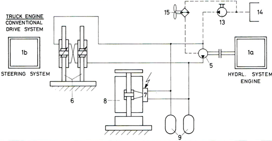
Hydraulic Flow Chart of the Vibrator-System VVB
Hydraulic Flow Chart of the Vibrator-System VVCA