Unser VVCA-Vibrator-System
2. Teil (Fortsetzung aus Report 2/75)
H. Werner, H. Talke
Der Hydraulikfachmann unterscheidet den Hauptölkreislauf (stark ausgezogene Linien), der von zwei Axialkolbenpumpen gespeist wird, und Hilfsölkreisläufe (gestrichelte Linien), die von Zahnrad pumpen versorgt werden Die Axialkolbenpumpen sind über eine Welle an den Motor angeflanscht, die Zahnradpumpen werden über Keilriemen angetrieben.
Der Konstrukteur eines Hydraulik-Systems muß die verschiedenen Baugruppen, Bauteile und Bauelemente wie z. B. Pumpen, Hubzylinder, Druckleitungen, Druckschläuche, Filter und Ventile anhand ihrer Kennwerte sorgfältig aufeinander abstimmen.
Wegen der im Hydraulik-System auftretenden Schwingungen, die durch den Vibrationsvorgang verursacht werden, bilden die Axialkolbenpumpen (2) und (5) (in Figur 4) mit dem hydrostatischen Fahrantrieb, dem Liftsystem und dem Vibrator einen geschlossenen Ölkreislauf (Hauptölkreislauf). Die Saugseiten der Pumpen sind nicht mit dem Öltank verbunden, was ja zu einer öffnung des Kreislaufs führen würde, vielmehr wird das öl den Pumpen über eine Doppelzahnradpumpe (13) und einen Hilfsölkreislauf unter Druck zugeführt.
Im Hauptölkreislauf wird zwischen Hochdruck-und Niederdruckseite unterschieden. Auf der Hochdruckseite (vor Eintritt des öls in den Verbraucher) herrscht ein Druck von ca. 210 atü, auf der Niederdruckseite (bei Austritt des öls aus dem Verbraucher) werden Drücke von ca. 10 atü gemessen. Oft müssen während einer meist 10stündigen Meßschicht bis zu 1000 Arbeitspositionen, die in der Regel nur wenige Meter voneinander entfernt sind, angefahren werden. Der hydrostatische Fahrantrieb (vollhydraulischer Allradantrieb) ist dem Arbeitsrhythmus des Fahrzeugs, der durch häufiges Anfahren und Abbremsen gekennzeichnet ist, angepaßt. Vorder-und Hinterachse (sogenannte Lenktriebachsen) können im Verbund sowohl gleich -als auch gegensinnig gelenkt werden. Dadurch wird das Fahrzeug trotz seiner Länge von 7,5 m sehr beweglich (Wendekreis 13,5 m) und steigfähig. Während die Hinterachse starr mit dem Rahmen verbunden ist, befindet sich zwischen Vorderachse und Rahmen ein vertikal angeordneter Drehkranz zum Ausgleich der Verdrehbelastung bei unebenem Gelände. Übergroße Reifen (Raddurchmesser 1,40 m) mit einem Spezialprofil ermöglichen den Einsatz auch in tiefgründigem Gelände, wobei die Flurschäden auf ein Minimum beschränkt werden können. Das Vibrator-System kann eine Geschwindigkeit von maximal 42 km/h erzielen. Obwohl das System in erster Linie für den Einsatz in schwierigem Gelände (z. B. Wüstengebiete) konstruiert worden ist, kann es auch auf Straßen und Wegen eingesetzt werden. Die gesetzlichen Vorschriften für die Teilnahme am Straßenverkehr sind hierbei beachtet worden.
Aus Sicherheitsgründen haben der Fahrantrieb und die Lenkung getrennte ölkreisläufe. Die Axialkolbenpumpe für den Fahrantrieb arbeitet als Verstelldoppelpumpe (2), an die ein Olmotor für die Vorderachse (3) und einer für die Hinterachse (4) angeschlossen sind. Die Verstelldoppelpumpe ist mit einer drehzahlabhängigen Kombinationssteuerung ausgerüstet. Sie kann nach Bedarf auf "Straßenbetrieb" oder auf "Meßbetrieb" eingestellt werden.
Second Part (continued from Report 2/75)
The design engineer of a hydraulic system has to match very carefully the different structural members, parts and elements, such as pumps, lift cylinders, pressure pipes, flexible pressure hoses, filters and valves, according to their characteristic values.
Because of the pulsations in the hydraulic system, which are caused by the vibration procedure, the axial-flow pumps (2) and (5) (in figure 4) form a closed oil circuit (main oil-circuit) with the hydrostatic drive system, the lift system and the vibrator. The suction sides of these pumps are not connected directly to the oil tank, which would have broken the circuit, but the oil is fed, under pressure, into the pumps by a double gear pump (13) and an auxiliary oil circuit.
In the main oil circuit one has to differentiate between the high-pressure side and the low-pressure side. On the high-pressure side there is apressure of about 210 atm, on the low-pressure side there is apressure of about 10 atm.
During one survey shift, usually 10 hours, up to 1000 working positions have often to be taken up which are generally only a few meters distant from each other. The hydrostatic drive system (fully hydraulic all-wheel drive) is adapted to the working rythm of the carrier, namely the frequent starting and braking. Front and rear axles (so called steering axles) can be steered independently. This makes the vehicle very mobile, despite its length of 7,5 m (turning circle 13,5 m) and provides an excellent climbing ability. While the rear axle is connected rigidly to the frame, there is an articulated ring connection, in a vertical position, between the front axle and the frame for the compensation of the torsional strain in rough terrain. Oversized tyres (wheel diameter 1,40 m) with a special tread allow the application of the vehicle in swampy terrain. Damage to cultivated fields can be restricted to aminimum. The vibrator system VVCA can reach a maximum speed of 42 km/h.
Although the VVCA has been designed, in the first piace, for use under difficult terrain conditions (for example in desert areas), it can also perform on public roads and tracks. The legal restrictions for the traffie regulations have also been taken into consideration.
For safety reasons, the drive system and the steering system have separate oil circuits. The axial-flow pump, belonging to the drive system, operates as an adjustable double pump (2) to which two oil engines are connected: one for the front axle (3) and another for the rear axle (4). The pump is equipped with a speed-dependent combinati on control. It can be adjusted to "road operations" (driving only) or to "survey operations" (driving and vibrating).
The vibrator lift system (6) which sets the vibrator down, thus putting it into working position, is a new PRAKLASEISMOS development. The function of the conventional column lift system is now carried out by a lever arm lift system. The principle of the lever arm lift system is shown in figure 6. Instead of two easily damaged lift columns of a conventional vibrator unit, whieh set down the vibrator and litt it by means of four cylinders attached to the chassis, the vibrator system VVCA is equipped with the practical maintenance free lever arm lift system. Only one cylinder is necessary for operation. It is also attached to the chassis.
Fig. 6 Prinzip des Liftarm-SystemsPrinciple of the Lever Arm System
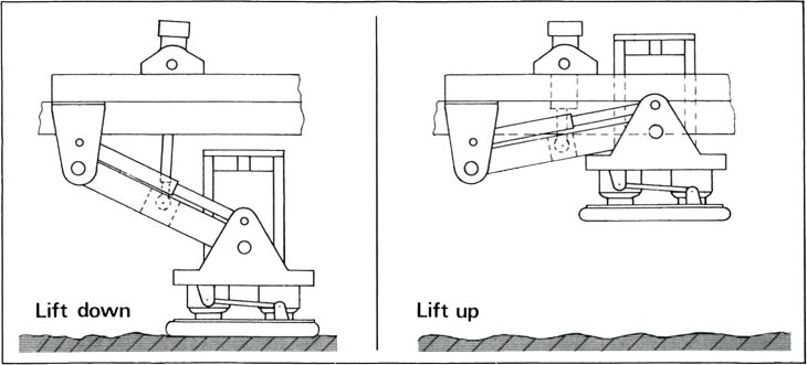
Neuartig ist das Vibratorliftsystem, das den Vibrator auf den Boden absetzt und in Arbeitsstellung bringt (6). Die Funktion des herkömmlichen Liftsäulensystems übernimmt nun ein in eigener Entwicklung konzipiertes Liftarmsystem Das Prinzip des Liftarmsystems ist aus Figur 6 ersichtlich. An die Stelle von zwei leicht beschädigbaren Liftsäulen bei der Vibrator-Anlage VVB, die im Verbund mit insgesamt vier am Fahrzeugrahmen befestigten Liftzylindern den Vibrator absetzen oder anheben, tritt beim VibratorSystem VVCA das praktisch wartungsfreie Liftarmsystem mit nur noch einem Liftzylinder, der ebenfalls am Fahrzeug rahmen befestigt ist. Während beim herkömmlichen Liftsäulensystem das Absetzen und Anheben des Vibrators von deutlich spürbaren Stößen begleitet ist, die sich dem Fahrerhaus und Fahrer mitteilen, ist beim Liftarmsystem von diesen unangenehmen Begleiterscheinungen kaum noch etwas zu spüren. Darüber hinaus verfügt das System über eine außerordentlich wirksame Schalldämpfung (-7 dB). Das System ist damit ausgesprochen "umweltfreundlich!".
In leichtem Gelände (Straßen, Wege) ist es nicht erforderlich, daß der Lift voll ausgefahren wird. Es genügt, wenn das Fahrzeugheck nur so weit vom Boden abhebt, bis die Vibratorbodenplatte voll belastet ist. Fahrer und Material werden geschont und Zeit wird gewonnen. Die Liftabschaltung kann "wegeabhängig" (Abschaltung, nachdem der Kolben eine vorher eingestellte Strecke im Zylinder zurückgelegt hat) oder " lastabhängig" (Abschaltung, nachdem eine bestimmte Last auf der Vibratorbodenplatte ruht) erfolgen. Um eine optimale Ankopplung der Vibratorbodenplatte an den Boden zu erzielen, ist sie gegenüber dem Liftarm bis zu einem bestimmten Winkel verstellbar.
Der Vibrator setzt sich im wesentlichen aus dem Steuerteil (7) und dem Reaktionsteil (8) zusammen. Er bildet mit der Axialkolbenpumpe (2) und den Hydrospeichern (9), einen geschlossenen Olkreislauf. In Figur 7 ist eine Prinzipskizze des Vibrators wiedergegeben. Der Vibrator selbst 'ist ein schwingungsfähiges Zweimassen-System. Die eine Masse ml besteht aus der Vibratorbodenplatte und dem angekoppelten Erdboden. Die Reaktionsmasse m2 (Gewicht 1600 kp) ist ein zylindrischer Block aus Spezial-Gußeisen mit einer seitlichen Anflachung, an die das Steuerteil angebracht ist. Die beiden Massen sind hydraulisch gekoppelt über einen Zylinder, der über eine Kolbenstange mit der Vibratorbodenplatte verbunden ist. Die Funktionsweise des Steuerteils zeigt die Figur 8. Im Steuerteil, auch Servo-Ventil genannt, wird das elektrische Signal in ein hydraulisches umgewandelt und dabei verstärkt. Das Servo-Ventil besteht aus dem elektromechanischen Teil, dem Torque-Motor, und dem hydraulischen Teil, einem zweistufigen 4-Wege-Ventil. Zur Zeit werden bei uns zwei verschiedene Typen des Torque-Motors (auch Drehmomentwandler genannt) verwendet: Der Torque-Motor der Firma Atlas und der Torque-Motor der Firma MOOG.
Beim Torque-Motor der Firma Atlas erfolgt die Vor-Steuerung des 4-Wege-Ventils über einen an einem Anker befestigten Stab (Pilot); der Anker befindet sich in einem Magnetfeld. Die Funktion des Stabes übernimmt beim MOOG-Torque-Motor eine am Anker befestigte Zunge, die Steuer-Düsen öffnet und schließt.
Die Masse mj, die sich aus der Vibratorbodenplatte und dem angekoppelten Erdboden zusammensetzt, ist, wie man sich leicht vorstellen kann, ein recht komplexes Gebilde, das mit einer idealen Masse, welche Bezeichnung die Reaktionsmasse m2 noch annähernd verdient, nichts mehr zu tun hat. Je nach der Qualität der Ankopplung der Vibratorbodenplatte an den Erdboden wird daher das Steuersignal bei der übertragung in den Untergrund mehr oder weniger stark verzerrt. Um Phasenverschiebungen zwischen den Soll-und Ist-Schwingungen des Steuersignais zu beseitigen, werden die Ist-Schwingungen an verschiedenen Stellen des Vibrators gemessen und in der Vibratorelektronik, die sich im Fahrerhaus befindet, automatisch nachgesteuert. So befindet sich auf der Vibratorbodenplatte ein Beschleunigungsaufnehmer, der seine Daten an einen Phasen kompensator weiterleitet. Signalrückkopplungen erfolgen über das Masse-LVDT (Linear Voltage Differential Transformer), das auf der Reaktionsmasse m2 angebracht ist, und das Servo-Ventil-LVOT, das sich am Steuerteil befindet. Damit sich die Schwingungen des Vibrators während des Vibrationsvorganges nicht auf das Fahrzeug mitteilen und umgekehrt die Reaktionsmasse m2 durch die Masse des Fahrzeugs unbeeinflußt bleibt, erfolgt die Abstützung des Fahrzeughecks auf die Vibratorbodenplatte über elastische Zwischenglieder. Beim System VVCA handelt es sich dabei um Luftfederbälge (Gummizylinder, die mit Druckluft gefüllt sind). Die Luftfederbalgfüllung erfolgt automatisch.
Für die überprüfung der Funktionsfähigkeit des Systems VVCA sind alle Anzeigeinstrumente übersichtlich auf einem Armaturenbrett im Fahrerhaus angebracht.
With the conventional column lift system the lowering and lifting is accompanied by the often troublesome " Whip Lash" . The lever arm lift system does not show this unwanted accompanying effect. Due to a very effective sound proofing (-7 dB) the VVCA may be called "Sound Pollution" free.
In easy terrain it is not necessary to run the lift up completely. It is sufficient that the rear of the vehicle is lifted until the vibrator base plate is fully loaded. Doing this, time and material are saved. The lift switching may be "distance dependent" (piston in the cylinder overcomes a certain distance) or "weight dependent" (the force on the vibrator base plate reaches a predetermined value). To get an optimum coupling of the vibrator base plate to the ground, the VVCA lift system provides a variable "surface to base plate contact angle".
The vibrator, mainly, consists of the control unit (7) and the reaction unit (8). In connection with the axial-flow pump (2) and the hydraulic accumulators (9), it forms a closed oil circuit. In figure 7 a principle sketch of the vibrator is shown. The vibrator itself is an oscillatory two-masssystem. One mass ml consists of the vibrator base plate and of the coupled ground. The reaction mass m2 (weight 1600 kp) is a cylindrical block of special cast-iran with a lateral flattening to which the contraI unit is connected. Both masses are hydraulically coupled via one cylinder which is connected to the vibrator base plate by a piston rod.
The function of the control unit is shown in figure 8. The electric pilot signal is transformed by the control unit, also called servo-valve, into a hydraulic one, thereby being amplified. The servo-valve consists of the electromechanic part, the torque converter and of the hydraulic part, a double-stage four-way valve. At present, we are using two different types of torque converter: the torque converter of Atlas Company and the torque converter of MOOG Company. The torque converter of Atlas uses a small rod pilot connected to an armature, -which moves in a magnetic field -for the control of the four-way valve. With the MOOG torque converter, the function of the pilot is replaced by a control tongue also connected to an armature. This tongue opens and closes tiny nozzles which are connected to the valve.
Fig. 7 Vibrator-Prinzip VVCA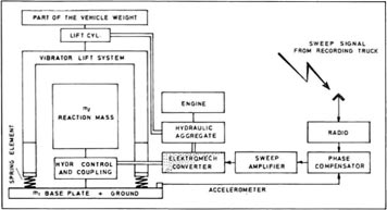
Fig. 8 Vibrator-Steuerung WCA
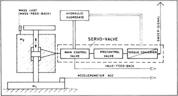
The mass m₁, which consists of the vibrator base plate and the coupled ground, is, as one can easily imagine, a very complex system, which has nothing to do with an ideal mass, a designation, which might be approximately valid for the reaction mass m₂ The grade of coupling of the vibrator base plate to the ground has an influence on the rate of distortion of the transmitted pilot signal. In order to eliminate phase shifts between the nominal and actual values of the sweep oscillations, the actual values are measured at different points of the vibrator and then used for automatic adjustment by the vibrator electronic unit, which is installed in the driver's cabin. On the vibrator base plate an accelerometer is attached, the data of which are transferred to a phase compensator. Signal feed back is executed by the mass LVDT (Linear Voltage Differential Transformer), which is on top of the reaction mass m2, and by the servo-valve LVOT connected to the control unit.
In order to avoid any transfer of oscillations of the vibrator to the vehicle and, on the other side, any influence of the vehicle to the reaction mass m2, the rear of the vehicle is propped up on the vibrator base plate by elastic intermediate members, with the VVCA system with air bags (rubber cylinders, filled with compressed air). The air bags are supplied automatically.
For the checking of all functions of the VVCA, all indicating devices are installed well-arranged on an instrument panel in the driver's cabin.